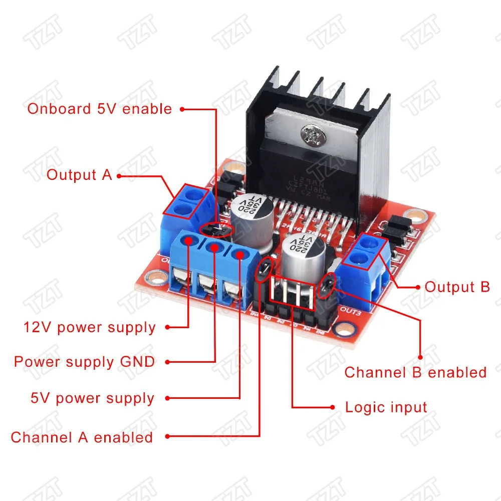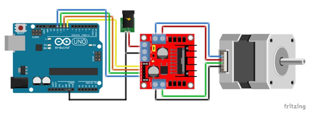

IN3 & IN4 pins are used to control spinning direction of Motor B. If both the inputs are either HIGH or LOW the Motor A will stop. When one of them is HIGH and other is LOW, the Motor A will spin. IN1 & IN2 pins are used to control spinning direction of Motor A. Removing the jumper and connecting this pin to PWM input will let us control the speed of Motor A. Pulling this pin HIGH(Keeping the jumper in place) will make the Motor A spin, pulling it LOW will make the motor stop. If the 5V-EN jumper is removed, you need to connect it to the 5V pin on Arduino.ĮNA pins are used to control speed of Motor A. If the 5V-EN jumper is in place, this pin acts as an output and can be used to power up your Arduino. Remember, if the 5V-EN jumper is in place, you need to supply 2 extra volts than motor’s actual voltage requirement, in order to get maximum speed out of your motor.ĥV pin supplies power for the switching logic circuitry inside L298N IC. The higher the duty cycle, the greater the average voltage being applied to the dc motor(High Speed) and the lower the duty cycle, the less the average voltage being applied to the dc motor(Low Speed).īelow image illustrates PWM technique with various duty cycles andaverage voltages. The average voltage is proportional to the width of the pulses known as Duty Cycle.
#DROK L298N MOTOR DRIVER CONTROLLER SERIES#
PWM is a technique where average value of the input voltage is adjusted by sending a series of ON-OFF pulses. A common technique for doing this is to use PWM (Pulse Width Modulation) The speed of a DC motor can be controlled by varying its input voltage.

Storage temperature: -25 Deg C ~ +130 Deg C The logical part of the operating current range: 0 ~ 36mA The logical part of the terminal supply area Vss: +5 V ~ +7 V (can take power within the board +5 V)

Using L298N made by ST company as the control chip,the module has such characteristics as strong driving ability, low calorific value and strong anti-interference ability.ĭriver: L298N Dual H Bridge DC Motor Driver ICĭriven part of the terminal supply area Vs: +5 V ~ +35 V such as the need to take power within the board, the supply area Vs: +7 V ~ +35 V The L298N driver module, using ST's L298N chip can directly drive two 3-30V DC motor, and provides a 5V output interface can 5V single-chip circuitry to supply, support 3.3VMCU control, you can easily control the DC motor speed and direction, you can also control the 2-phase stepper motor, smart car essential.


 0 kommentar(er)
